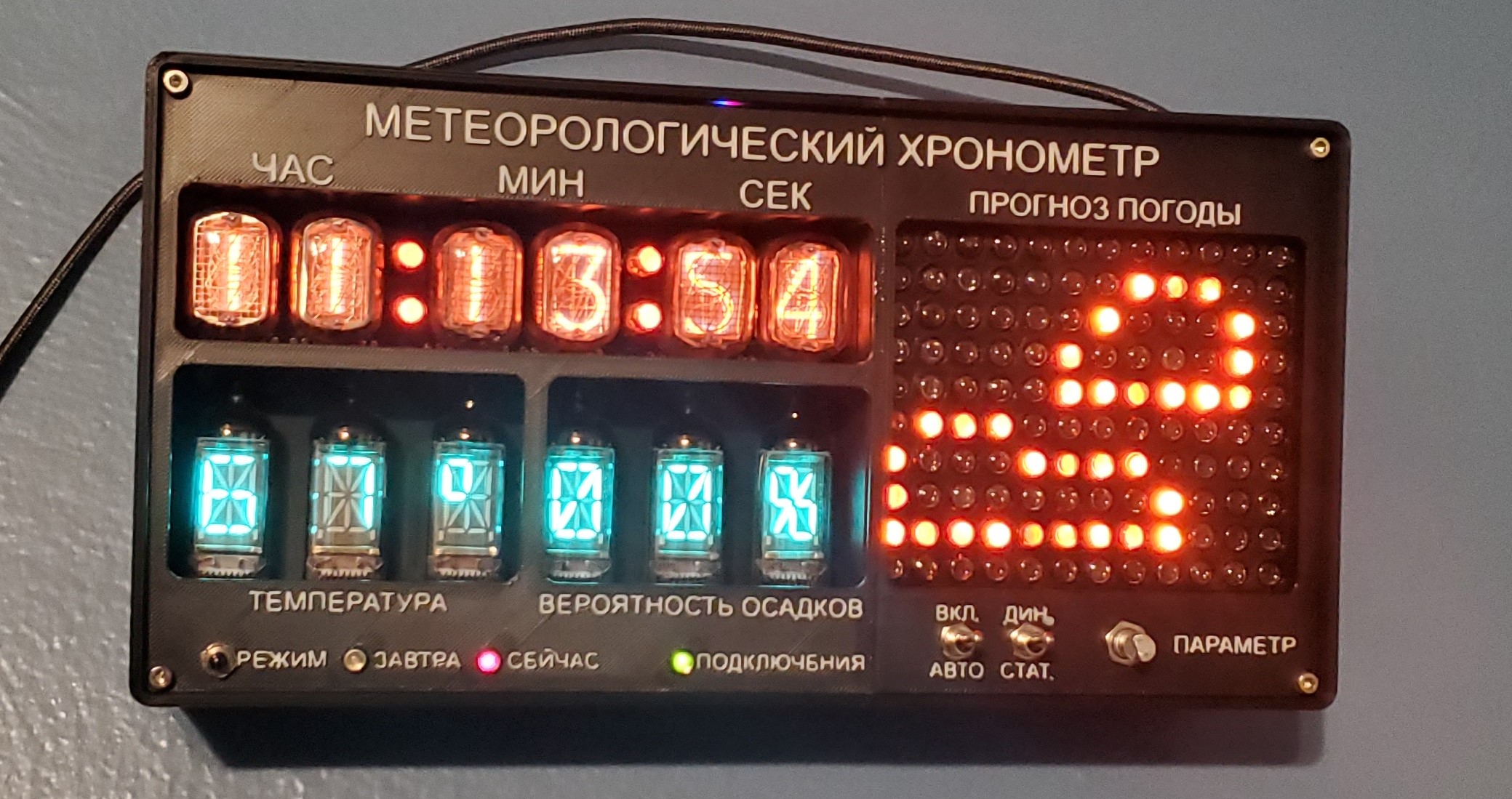
Nixie and VFD Weather Clock
This project is mostly finished. I still want to modify some of the animations I created
and replace the 3D-printed front panel with one made from aluminum.
Project GitHub Repository

This clock is powered by an ESP32 and features an IN-12 Nixie tube clock, a 12×10 INS-1 neon indicator matrix, and a six-character IV-17 VFD display. It retrieves time and weather data from the internet at regular intervals and can display either current or future weather, or cycle between both. The current weather time frame being displayed is indicated by an AL102 LED.
All of the displays, including the LEDs, are Soviet surplus, so I wanted the clock to resemble an old piece of Soviet military equipment. All front panel lettering and messages displayed on the alphanumeric IV-17 tubes are written in Russian.
This clock incorporates three circuit boards I designed, plus one additional hand-made
board.
Nixie Tube Board - A variation
of my
Nixie tube clock board, designed to be
smaller and accept input via a connector.
IV-17 VFD Board
INS-1 Matrix Board
All board designs and Arduino libraries are available on GitHub.
For the high-voltage power supply, I use an NCH6300HV by Omnixie. I used their older design in my first Nixie clock and was pleased with its performance.
The clock is powered by 12V through a USB-C connection. A small power trigger board
requests 12V from the USB adapter.
When the adapter is first plugged in, 5V is supplied to the clock. Some voltage reaches
the 7805 voltage regulator that powers the ESP32, but not enough to turn it on. After a
few
seconds, the voltage increases to 12V, and the ESP32 begins bringing up the other power
supplies.
I have not encountered any issues with this arrangement.
A buck converter generates the 2.4V required for the VFD filaments, while a boost converter produces the 25V needed for the anode voltage. A linear regulator provides 5V for the VFD and Nixie board, which also powers the ESP32.