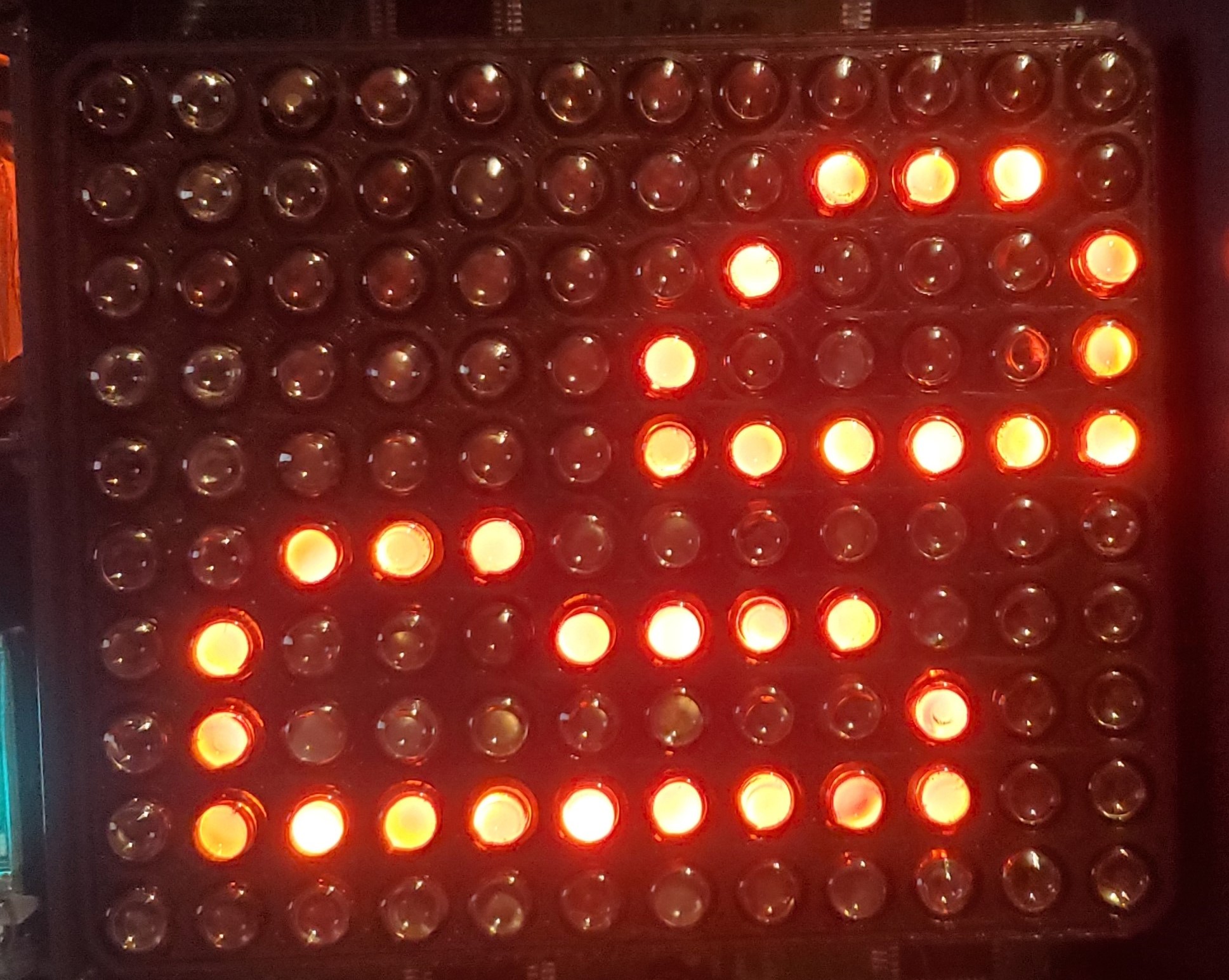
INS-1 Nixie Tube Matrix
Code and board design files: GitHub Repository
Project where the board is used: Nixie and VFD Weather Clock
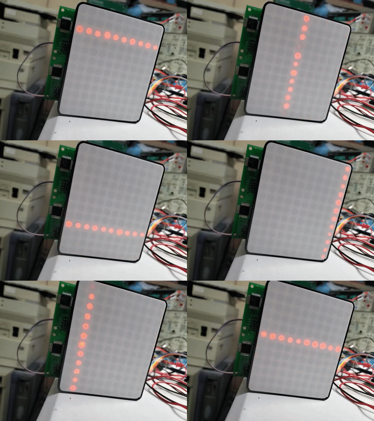
This project was inspired by the excellent Neon Pixels project. I designed my own board because Neon Pixels seemed too difficult to build.
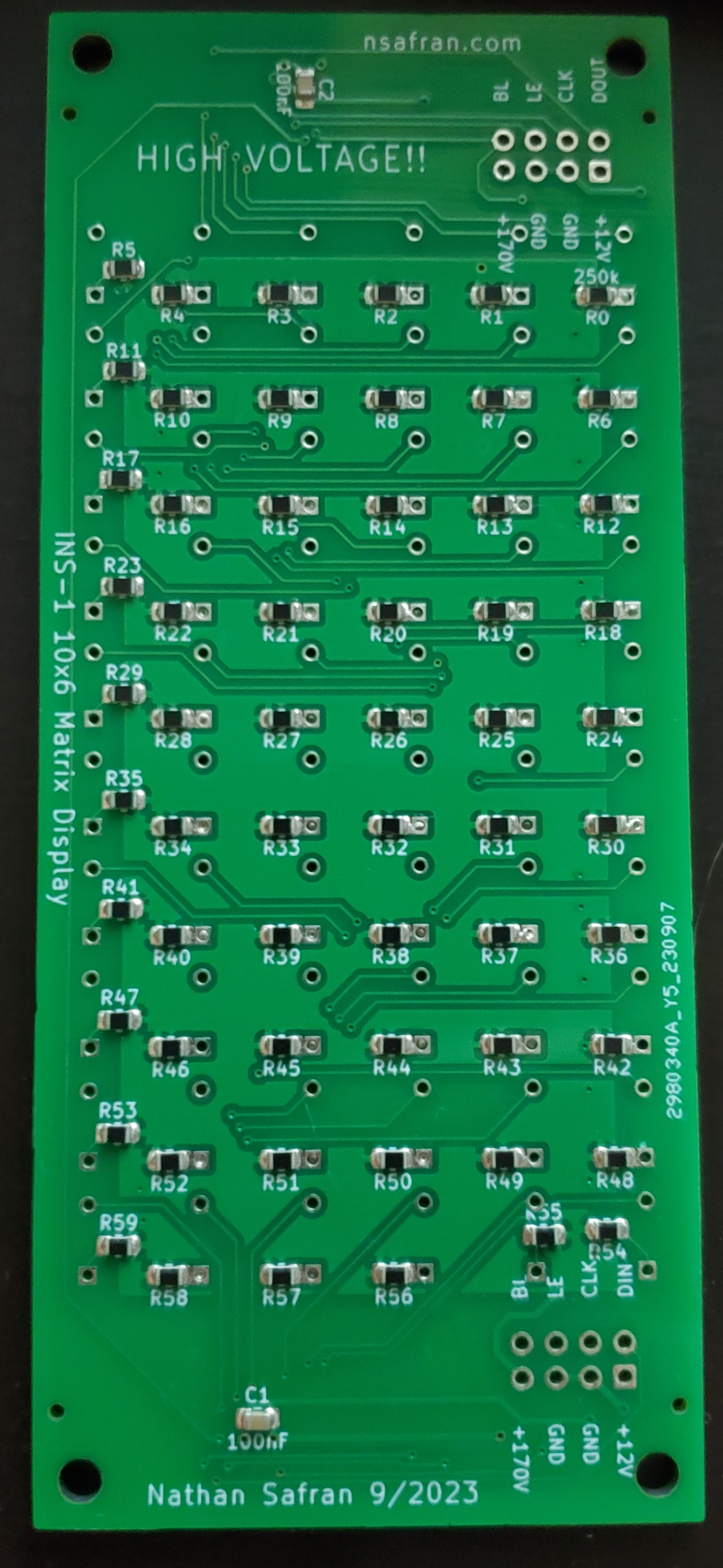
This board is a 6x10 matrix of INS-1 (ИНС-1) Nixie tube indicators. I chose a 6x10 layout because I wanted to use the board to display weather icons (clouds, sun, rain, etc.). Combining two boards creates a 12x10 display, providing enough resolution for basic graphics while keeping the physical size manageable. The 6x10 design also utilizes most of the outputs on the shift registers, with 60 tubes per board.
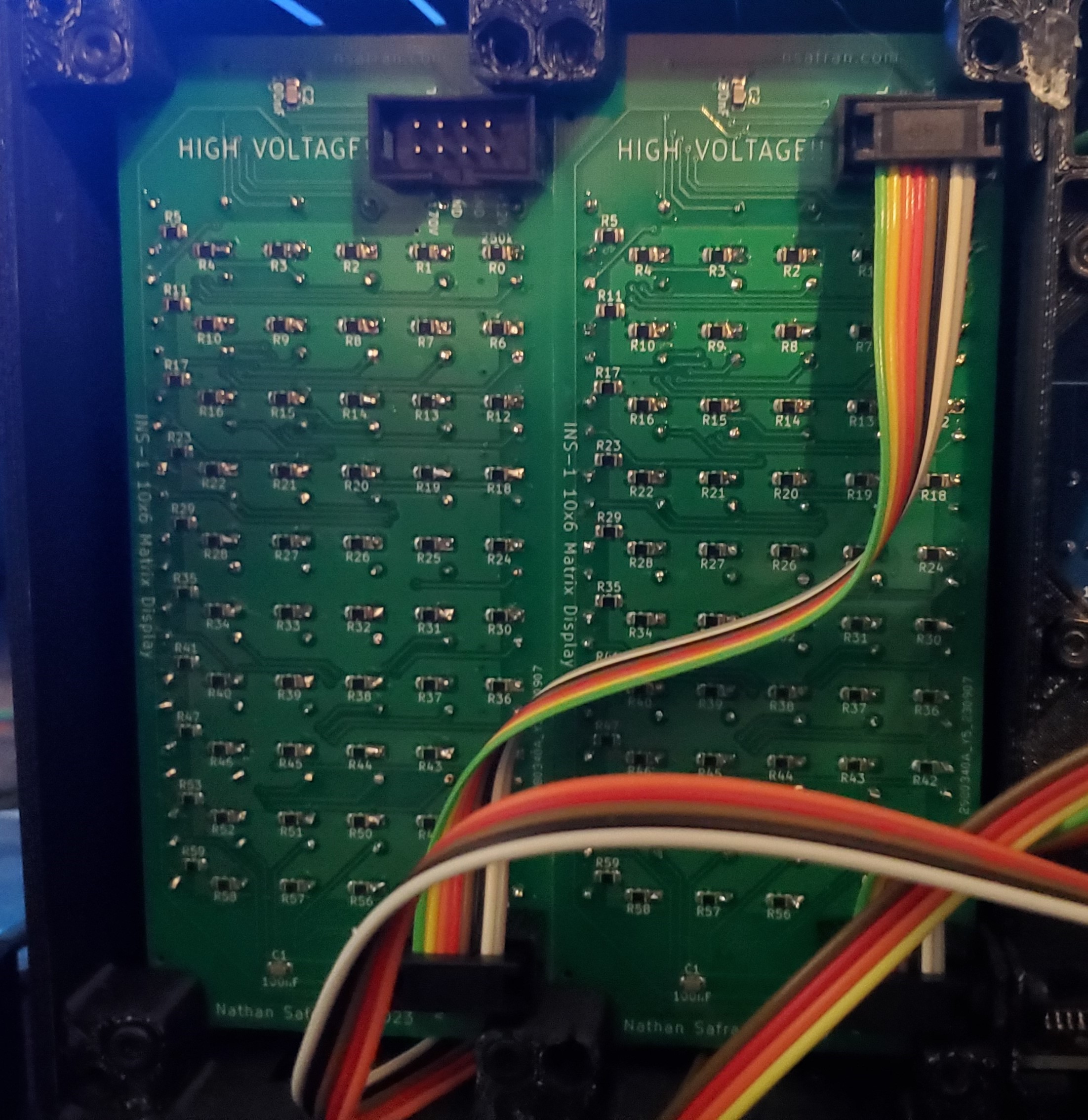
To control the tubes, I used HV5530 32-bit high-voltage shift registers. Power (both
high voltage and 12V) is supplied through the input connector. The displays are
chainable via a simple 8-pin connector.
I wanted to make the board smaller, but there was no room to place the chip or route the traces.
This was the first board I had assembled by JLCPCB. They handled the resistors and capacitors, which was well worth the cost. Soldering the HV5530 by hand was not too difficult.
Design Mistakes
While designing this board, I made two major mistakes:
- I connected the polarity (POL) pin on the HV5530 to GND. Since POL is active low, this caused all bits to be inverted. I initially did this because I knew I would be driving the logic signals through transistors, which also invert the signal. However, this setup caused the BLNK pin to light up the display when it was active, eliminating any possibility of PWM dimming. To fix this, I disconnected POL from GND and ran a bodge wire to 12V. This has been corrected in the KiCAD design files, and the code has been adjusted accordingly.
- I placed the anode resistors too close to the plated through-holes for the tubes. When JLCPCB assembled the board, solder from the resistors flowed into the holes, requiring me to manually remove solder from most of the anode holes before inserting the tubes. If I produce more of these boards, I will likely redesign them to fix this issue. This change has not yet been applied to the KiCAD files.
Image Design Program
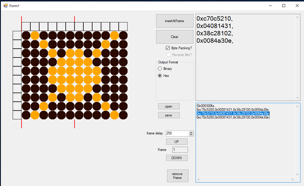
I created a sloppy C# WinForms program to help design images and animations for the
matrix display.
The program allows users to define a custom display size and number of displays. It
makes several assumptions about the display, so it's only useful for this project.
Features include:
- Saving and loading images/animations from JSON files
- Scrolling through animation frames
- Deleting frames
- Setting frame duration (in milliseconds)
- Accurately counting the number of frames in an animation
- Generating formatted C++ code that can be pasted directly into Arduino source files
I'm sure there are better ways to accomplish this, but this was the solution I came up with.
