INS-1 Nixie Tube Matrix
Code and Board design files: https://github.com/nsafran1217/INS-1_Matrix
Project where the board is used: Nixie and VFD Weather Clock
This was inspired by the excellent Neon Pixels project
I designed my own board because Neon Pixels seems too difficult to build.
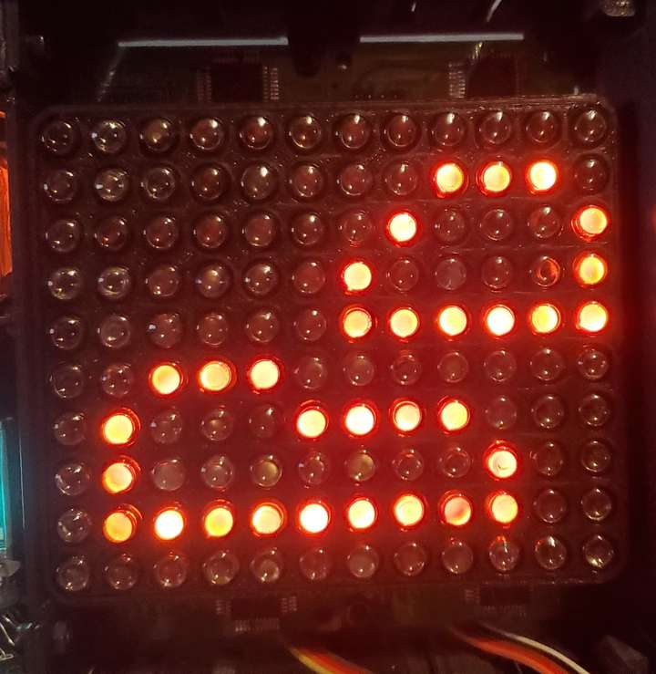
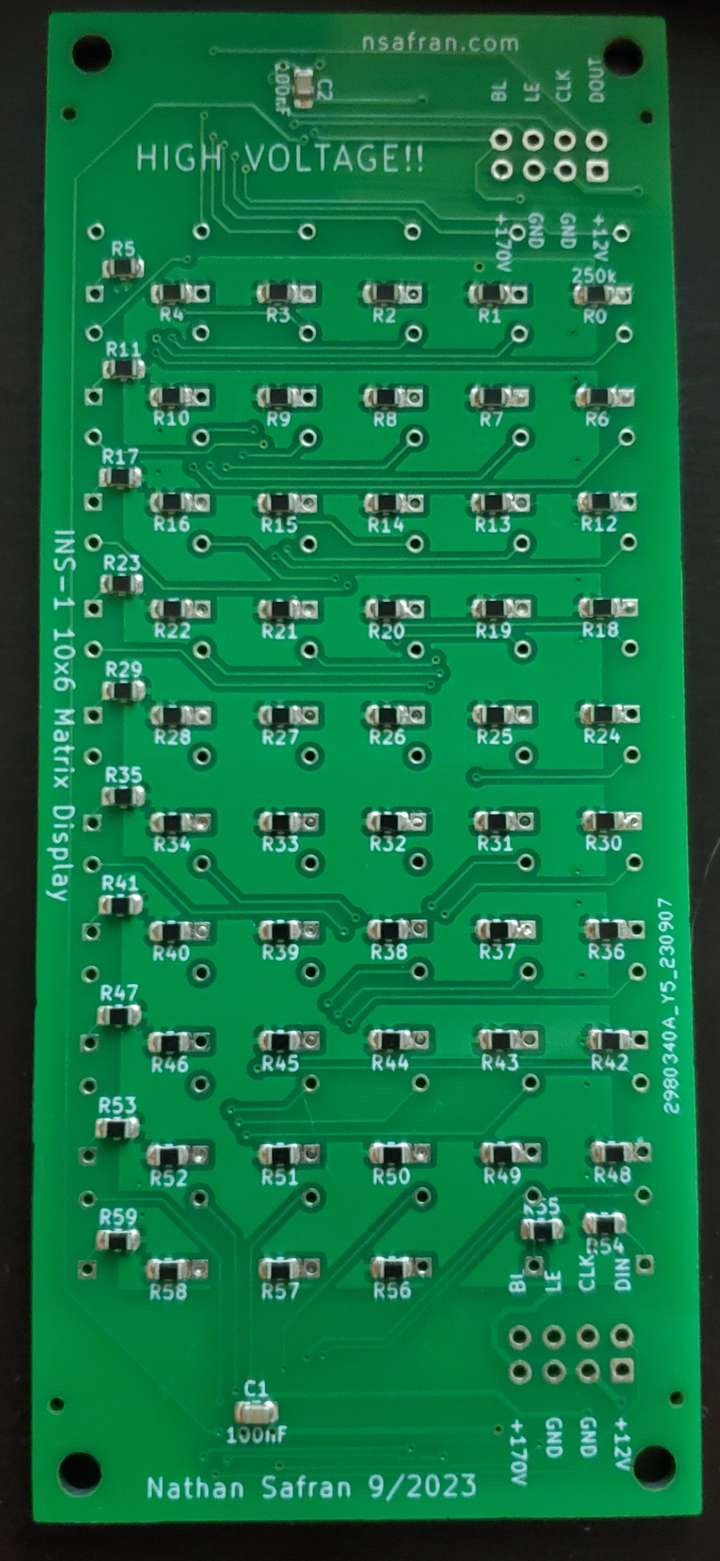
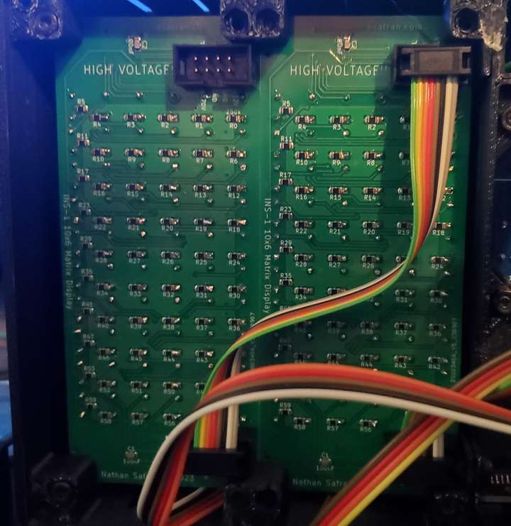
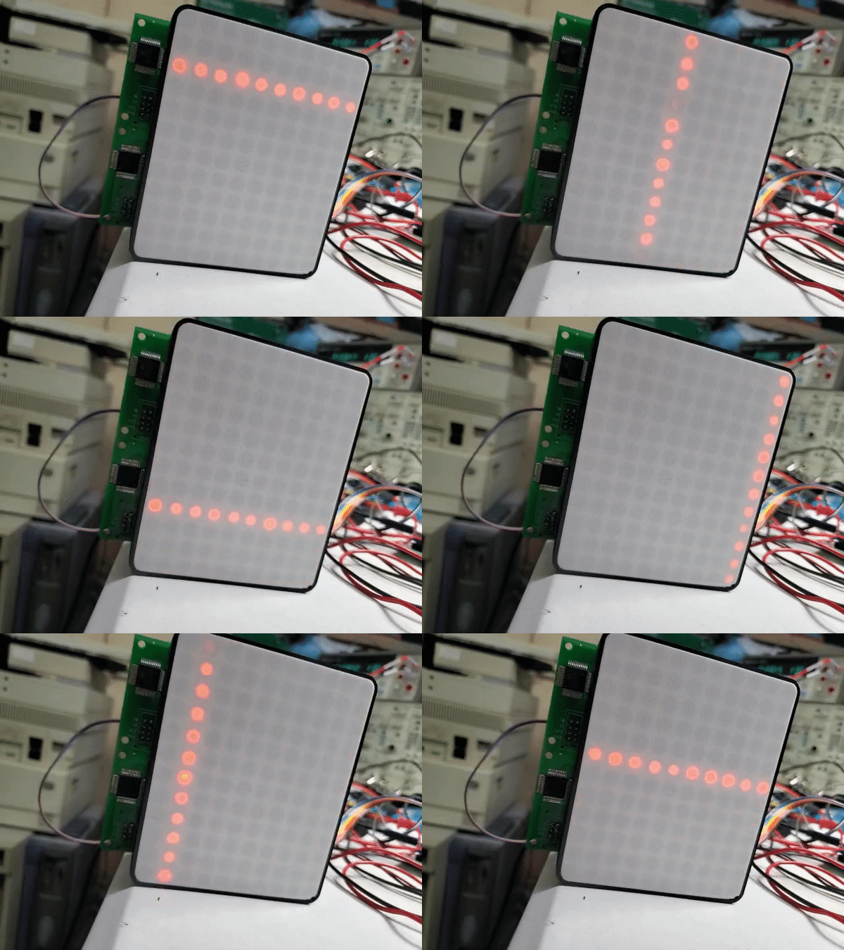
This board is an 6x10 matrix of INS-1 (ИНС-1) Nixie tube indicators. I chose 6X10 because I wanted to use the board to display weather icons (a cloud, the sun, rain, etc.). Putting 2 together would give me a 12x10 display, which gave enough pixels to play with and wasn't too physically big. 6x10 also is 60 tubes per board, so we used most of the shift register outputs.
I used HV5530 32-bit high voltage shift registers to control each tube. The HV and 12V supply for the board would be provided on the input connector. I made the displays chainable with a simple 8 pin connector.
I wish I was able to make the board smaller, but there was no where to put the chip or route the traces.
This was the first board where I had JLCPCB assemble the boards. They did all the resistors and capacitors, which was well worth the money. Soldering the HV5530 by hand was not too difficult.
I made two big mistakes on this board.
- I connected Polarity on the HV5530 to GND. POL is active low, so all bits were inverted. I did this because I knew I'd be driving the logic signals through transistors which would invert the signal, but this cause the BLNK pin to light the display when it was true, which removed any possibility of PWM dimming. I ended up disconnecting it from GND and running a bodge wire to 12V. I have fixed this in the KiCAD design files so it is connected to 12V, and the code is setup to account for this.
- I put the anode resistors too close to the plated through holes for the tubes. When JLCPCB assembled the board, the solder from the resistors flowed into the holes. I had to suck the solder out of most of the anode holes for the tubes. If I ever build more of these board, I will probably have new ones made. I have not fixed this in the KiCAD files yet.
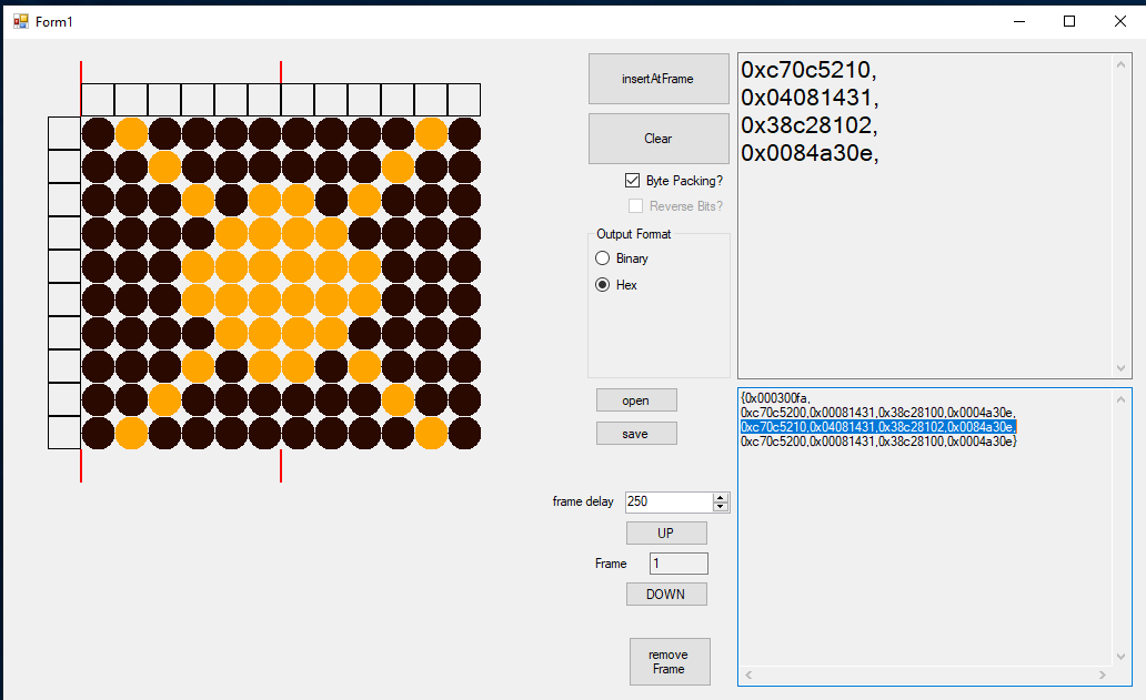
Image Design Program
I made a very sloppy program in c# with winforms to help design the images/animations and generate the arrays for the matrix display.
This program allows you to input a custom display size, and number of displays. It makes many assumptions about the display, so its really only usable for this project.
It supports saving and loading images and animations from JSON files, scrolling through the animation, deleting frames, specifying the frame time in ms, and properly counts the number of frames in the animates. It provides formatted code that you can paste directly into your Arduino source files. You just need to define the array.
I'm sure there's an easier way to do this, but this is what I came up with.
